Bringing the Grassroots back to Grassroots and recognising their thirst for DIY, our unique business-model is to make readily available each and every individual component required to build/rebuild dampers; unlike our competition, this is something we actively encourage. Our aim at YCW Suspension is to offer a full knowledge base for grassroot racers to calculate, build and tune their own dampers to meet their requirements. And thus, the YCW Suspension "Dry Kits" were born; highly customisable, highly cost-effective with unlimited tuning potential. For similar cost to a budget coilover kit and a few hours of your time (infact, with enough practise, you can knock out a damper in only 15mins), you can have a fully-bespoke coilover kit that could otherwise cost you thousands! Of course, if DIY is not up-your-alley, we also work directly with several specialist builders that will be more than happy to help you build your dampers for you for a fee. All of these builders have been assessed and certified by YCW Suspension, so you can rest-assured that they will do the job properly.
With the correct, high-quality components and the specialist tools/guides provided by YCW Suspension free-of-charge, no longer is damper building/tuning a "Black Art" reserved for big-budget race teams; basic garage tools and a day getting your hands oily is sufficient enough to build a set of dampers that will outperform most off-the-shelf coilover kits on the market. In fact, with a little bit of future investment and practise, your dampers can outperform the majority of the "big brand" coilover kits as well, and you will never again have to pay another company hundreds of dollars to rebuild your dampers for you when servicing time comes.
Please Note: This section is a work-in-progress, but will be constantly updated with more content and the latest tuning & assembly techniques to help our customers. Although very text-heavy at the moment (good for us old geezers, not so much for millennials), we are working on adding more diagrams as well as making a video-series to explain what we cover in our guides. To view our current [text] guides, please navigate using the sections below.
As the saying goes, we need to learn to crawl before we learn to walk. That couldn't be any more true when it comes to building a damper, so we have taken it upon ourselves to teach the community the basics of what a damper consists of (the components) and how the individual components work together to make a functioning damper. We have tried to keep the terminology as simple as possible, so whether you are a complete beginner at this, or you are an established company selling mass-manufactured kits, there is always something new to learn. So now we begin...
Please Note: Apart from some proprietary features here and there, for the most part, monotube damper design is very basic/generic and applies to 99% of what's available on the market.
Damper Body
Before we continue further, we would like to debunk a very common misconception about dampers/coilovers. One of the questions we get asked a lot is "Do your coilovers have fixed or adjustable lower mounts?". Why do we get asked this so much? Well, the main reason why we are asked this is because certain companies like to promote the myth that if a damper has an adjustable lower mount, it's basically a Chinese knock-off that utilises generic one-size-fits-all dampers, and if it has a non-adjustable lower mount, then it has been designed specifically for that vehicle. This could not be further from the truth, and is simply a marketing ploy. One of our competitors once publicly said; "customers are stupid and don't know what they need, so because we win a lot of races, if they want to win, they have to use what we tell them to". Talk about arrogance! Let us explain:
Please Note: Apart from some proprietary features here and there, for the most part, monotube damper design is very basic/generic and applies to 99% of what's available on the market.
Damper Body
- Top Cap with wiper seal. Not 100% mandatory, but this helps clean the piston rod of any dust/debris before it enters the damper body
- Seal Guide with rod seal (some designs integrate the top cap and seal guide together). This is what basically guides your piston rod in/out of the damper body, limiting any lateral play and preventing the oil from leaking out the top
- IFP (Internal Floating Piston). This is what separates the oil chambers from the gas chamber
- Base/Head Valve (also called a compression valve). Typically only higher end dampers use this (2-way adjustables). Allows you to reduce internal pressures, which decreases hysteresis and increases damper response
- Bottom cap (sometimes integrated into the lower mount). Some brands use self healing rubber (not recommended, as they are prone to leaking and are impossible to pressure tune), whereas some use schrader valves (recommended. Minimal leakage and much more accurate for pressure tuning)
Before we continue further, we would like to debunk a very common misconception about dampers/coilovers. One of the questions we get asked a lot is "Do your coilovers have fixed or adjustable lower mounts?". Why do we get asked this so much? Well, the main reason why we are asked this is because certain companies like to promote the myth that if a damper has an adjustable lower mount, it's basically a Chinese knock-off that utilises generic one-size-fits-all dampers, and if it has a non-adjustable lower mount, then it has been designed specifically for that vehicle. This could not be further from the truth, and is simply a marketing ploy. One of our competitors once publicly said; "customers are stupid and don't know what they need, so because we win a lot of races, if they want to win, they have to use what we tell them to". Talk about arrogance! Let us explain:
- Damper bodies are almost always cut to size from steel/aluminium tubes. They are not CNC machined from a piece of billet, as doing so would increase the cost ten-fold. No manufacturer in their right mind would do this
- As the damper body is simply cut to length, this means that most manufacturers will have available a large range of different body lengths to choose from
- As the damper body is simply a tube, and not CNC machined from a piece of billet, the lower mount is always added on to the end, be it threaded on (steel & aluminium) or welded on (steel)
- Besides the length of the damper body (which the manufacture can choose/determine based on the customers requirements), the only part that is vehicle specific are the mounts; in this case, the lower mount
- It is up to the manufacturer to decide how long they want the mount to be, and whether it is adjustable or not. Some companies (like ourselves) let the customer choose what type of mount they want. The damper in our shock dyno video above is an example of a fixed, non-adjustable, lower mount
- Most European manufacturers offer fixed-mounts not because they are better, but simply because of TUV regulations (i.e the overall damper length must be the same as oem, and non-adjustable). Infact, these same manufacturers offer dampers with adjustable lower mounts on all of their non-TUV applications (i.e race use only)
- Whether the lower mount can be adjusted on the damper body or not, it does not change the outcome; it is the lower mount that has been designed specifically for the vehicle (otherwise it won't fit), not the damper body
- Besides TUV regulations, there is no advantage to using a fixed mount (unless you are talking about non-reservoir 2-way adjustable dampers, which have no choice). Infact, provided the damper has been designed/assembled/pressure-tuned properly, an adjustable mount is superior as it allows you to adjust ride height and/or wheel:bump ratio without affecting your bump:droop ratio. The lower spring perch is primarily used to change your bump:droop ratio, not your ride height. Fixed mount dampers are forced to do this, which is not the correct way
- In conclusion, unless TUV-regulation is a requirement, you should almost always choose a damper with an adjustable lower mount
- Adjuster. Usually consists of 2 parts: External knob and the internal threaded adjuster with detents
- Bleed rod. The threaded adjuster will either move this further down the piston rod to decrease bleed, or allow the bleed rod to move back up the piston rod to increase bleed due to the sprung bleed needle
- Bleed needle. This is moved in/out of the jet valve by the bleed rod. There is a spring between the needle and jet, which keeps the needle compressed upwards against the needle rod
- Jet Valve. This is the "oil bypass" (i.e bleed) that allows the oil to flow directly between the compression and rebound chambers without having to pass through the piston. The volume of flow (i.e bleed) is determined by how much the bleed needle is inserted into the top of the jet valve
- Some damper designs do not use a needle valve design, but instead, use a rod/washer design that rotates to open/close orifices to control the bleed
- Main piston (also called the mid-valve). Different types of piston will determine the type of damping (e.g linear, progressive, digressive, regressive etc)
- Shim stack. By changing the size, thickness and number of shims, this determines how much damping force there is. There are shims on both sides of the piston; one stack for compression and one stack for rebound
- First of all, forget everything you've read about dampers/shock absorbers. You only need to know one thing, and that is "the sole purpose of a damper is to control the rate at which the coupled spring compresses or extends". That is it. Not to control body roll, not to control stiffness, not to absorb shock. It is a "speed controller" for your springs, plain and simple.
- When your damper compresses, the rod goes into the damper body and flows through the oil. This in effect displaces the oil from the compression chamber into the rebound chamber. The rate at which this happens is first determined by the amount of bleed, and then how much resistance there is through the piston & shim stacks. This is the basis of how a damper operates
- As your damper is a 100% sealed component (or should be anyway), and you are decreasing the internal volume due to the piston rod entering the damper body, the displaced oil must go somewhere. As it can't leave the damper body, and thus internal oil volume cannot be changed, this is compensated for by the oil forcing the IFP further into the damper body and thus compressing the gas in the gas chamber (subsequently decreasing the gas chamber volume). Smaller volume + same amount of gas = higher pressure. As will be explained later, this plays a significant role in pressure tuning
- When your damper extends back (rebounds), the reverse of the above happens, and internal pressure decreases
- This is what most people are familiar with. By adjusting the "knob", you are simply adjusting the amount of "oil bypass" i.e bleed. This is what controls your low speed damping, which in turn will affect the rest of the damping curve. Depending on the type of jet valve used, this could be rebound only, compression only or simultaneous rebound/compression (in our opinion, not recommended and does more damage than good). The less bleed you have, the higher the damping force as less oil can flow through the bypass and is thus forced to flow through the piston
- For those lucky enough to own a 2-way adjustable, this knob is what allows you to adjust your compression valving independently of your rebound valving. This is the correct way to adjust compression, and not via an open jet valve (which adjusts compression/rebound simultaneously). If you're wondering why, it all comes down to pressure tuning, which we will expand on later in this guide
One of the most common questions that we are asked is "How do I determine what spring rates to use?". Unfortunately, this is a very subjective topic; what may be comfortable for one person, may be too stiff for another. Unlike our competition, that recommend spring rates based solely on what they think a spring rate will feel like, at YCW Suspension, we run our spring rate calculations based on natural ride frequencies for that particular vehicle and the drivers requirements
OEM front/rear balance & Aftermarket Swaybars
One question in particular that we get asked a lot is "is flat ride better?". For those that are unfamiliar with this term, it's a certain methodology where you calculate the rear ride frequency to be higher than the front (typically around 0-0.2hz), reason being that it allows your rear to "catch up" with the front over bumps, thus keeping your car flat. Our answer; it depends. For street cars, we try to stick as close as possible to the OEM front/rear balance in order to keep the car balanced and similar to the OEM setup. By deviating from this, you run the risk of created too much Understeer or Oversteer, which is generally a bad thing. When this happens, the customer then ends up chasing their tail and updating other components such as swaybars in order to compensate. Aftermarket swaybars are used as a fine-tuning tool only; always sort your dampers/springs/bushings out first before touching your swaybars. Our advice has always been "Don't be the 99%. Be the 1%; do it right first time". For a track car, it simply comes down to the understeer/oversteer characteristics that the driver prefers. What may be suitable for one driver, may be unsuitable for another
Suspension Frequency
Depicting the speed at which the suspension will compress and return to height, or cycles per minute, everyone has their own comfort zone and tolerance to this. In general though, it follows the below:
Please Note: All variables are in metric units
If manual calculations are not your forte, please feel free to play around with our Chassis Calculator.
OEM front/rear balance & Aftermarket Swaybars
One question in particular that we get asked a lot is "is flat ride better?". For those that are unfamiliar with this term, it's a certain methodology where you calculate the rear ride frequency to be higher than the front (typically around 0-0.2hz), reason being that it allows your rear to "catch up" with the front over bumps, thus keeping your car flat. Our answer; it depends. For street cars, we try to stick as close as possible to the OEM front/rear balance in order to keep the car balanced and similar to the OEM setup. By deviating from this, you run the risk of created too much Understeer or Oversteer, which is generally a bad thing. When this happens, the customer then ends up chasing their tail and updating other components such as swaybars in order to compensate. Aftermarket swaybars are used as a fine-tuning tool only; always sort your dampers/springs/bushings out first before touching your swaybars. Our advice has always been "Don't be the 99%. Be the 1%; do it right first time". For a track car, it simply comes down to the understeer/oversteer characteristics that the driver prefers. What may be suitable for one driver, may be unsuitable for another
Suspension Frequency
Depicting the speed at which the suspension will compress and return to height, or cycles per minute, everyone has their own comfort zone and tolerance to this. In general though, it follows the below:
- 1.0-1.5hz: Referred to as the Comfort Zone, this is what your typical everyday street/family car will be set at. Comfortable to drive on the street, but lacks steering response and chassis control
- 1.5-2.0hz: Referred to as the Sport Zone, this is what your typical everyday sports car will be set at. This is what we recommend for our street car/weekend warrior customers (typically between 1.8-2.0hz). Comfortable to drive on the street, yet offering precise steering response and chassis control
- 2.0-2.5hz: Referred to as the Non-Aero Race Zone, this is what your typical supercar or non-aero track car will be set at. Although still driveable on the street, this will feel harsh over bumps and is generally only recommended for track cars
- 2.5-3.0hz: Referred to as the Aero Race Zone, this is what your typical aero track car will be set at. Not recommended for a street car. Non-aero track cars will suffer from decreased traction in this zone
- 3.0hz+: This is what a dedicated pro race car will be set at and is far too harsh to use on the street. Non-aero track cars will fly off the track due to lack of traction
Please Note: All variables are in metric units
- 1kgf/mm = 9806.65 N-m. So if you have a 10K (kgf/mm) spring, this is 98,066.50 N-m. To convert lbs/in to kgf/mm, divide by 56
- Wheel Rate = Spring Rate (N-m) * Motion Ratio². This is the motion ratio of your damper, and varies between vehicles. Most MacPherson struts will be around 0.97, so using this as an example, 98,066.50 * 0.9409 = 92,270.77 N-m
- Frequency (hz) = 0.16 * √(Wheel Rate (N-m) / Corner Weight (kg)). So if your sprung corner weight is 400kg, 0.16 * 15.19 = 2.43hz
- From this, we can conclude that this particular example would put your natural ride frequency into the Non-Aero Race Zone
If manual calculations are not your forte, please feel free to play around with our Chassis Calculator.
Having the correct valving profile for your particular application is the single most important factor that determines the comfort/performance of your dampers. In order to reduce development costs, all of the mass-market manufacturers use generic valving profiles based off of the chosen spring rate for each and every vehicle application. While this may initially seem like an acceptable practice, and for a lot of vehicles it does fall within the ballpark requirements (especially for the everyday street car), there are two reasons why this is inaccurate and why we at YCW Suspension do not follow this practice; motion ratios & corner weights.
In laymans terms, what the motion ratios depict is how efficient your vehicle is in utilising the chosen spring rate, which determines the valving profile required. The closer to a 1:1 ratio (i.e the distance your piston rod moves vs the distance your wheel moves), the more your vehicle is utilising the spring. The less your vehicle is utilising the spring, the greater damping force required. To give an example:
For a given corner weight of 700lbs and a 6kgf/mm spring rate
Fun Fact: Have you ever wondered why most budget coilovers for the early model (90's era) Japanese cars generally have acceptable comfort/performance, whereas for later model cars (and especially the European cars) the comfort/performance was abysmal? It's because the valving profiles for the early model Japanese cars were developed by the original Japanese tuning companies (e.g A'PEXi) before they outsourced the manufacturing to Taiwan and South Korea. After this happened, these mass-market coilover manufacturers, unable to develop their own valving profiles, simply used the same valving profiles that they were originally given by the Japanese tuning companies and have applied them to every vehicle application since!
As a grassroots-orientated company, we understand how difficult it can be for the savvy suspension enthusiast to trawl through the internet for days on end and try to make heads or tails of all the information presented to them. We also understand, from a business perspective, why most suspension specialists will want to keep their valving-theories a closely guarded secret. However, we are not your typical suspension specialist; we actively encourage dialogue, questions and feedback on our tuning methodology and, if there is room for improvement, we are the first to test any new theories. If we are wrong about something, we will gladly admit it. Whether a company has 5 years of experience or 30 years of experience, there is always something new to learn. What makes the difference between a good company and a great company is not only experience (as the saying goes, doing something wrong 1000 times doesn't make it right), but the willingness to learn and apply new things. The best way to do this? Openness and sharing ideas as a community
To help our community choose the most suitable valving profile, we’ve written down the formulas below that will help determine what damping forces are required for your particular setup and requirements. Please note that the calculations will provide you with the 100% critical damping forces, that is, the force required for your damper to dissipate the energy stored in the spring in 1 cycle. If it takes several cycles, this means your damper is under-damped (which is what causes bounciness i.e the Cadillac pogo effect, and loss of body control). If it takes less than 1 cycle, this is classed as over-damped (this is what causes harshness and loss of traction).
Please Note: All variables are in metric units
So what do I set it at then? This varies depending on surface conditions and your requirements, but a good starting point is:
How to read a dyno graph
If manual calculations are not your forte, please feel free to play around with our Chassis Calculator.
In laymans terms, what the motion ratios depict is how efficient your vehicle is in utilising the chosen spring rate, which determines the valving profile required. The closer to a 1:1 ratio (i.e the distance your piston rod moves vs the distance your wheel moves), the more your vehicle is utilising the spring. The less your vehicle is utilising the spring, the greater damping force required. To give an example:
For a given corner weight of 700lbs and a 6kgf/mm spring rate
- A vehicle with a motion ratio of 1 would require 49lbs of damping force at a damper velocity of 1 in/sec
- A vehicle with a motion ratio of 0.5 would require 98lbs of damping force at a damper velocity of 1 in/sec
- A vehicle with a motion ratio of 1 would require 59lbs of damping force at a damper velocity of 1 in/sec
- A vehicle with a motion ratio of 0.5 would require 118lbs of damping force at a damper velocity of 1 in/sec
Fun Fact: Have you ever wondered why most budget coilovers for the early model (90's era) Japanese cars generally have acceptable comfort/performance, whereas for later model cars (and especially the European cars) the comfort/performance was abysmal? It's because the valving profiles for the early model Japanese cars were developed by the original Japanese tuning companies (e.g A'PEXi) before they outsourced the manufacturing to Taiwan and South Korea. After this happened, these mass-market coilover manufacturers, unable to develop their own valving profiles, simply used the same valving profiles that they were originally given by the Japanese tuning companies and have applied them to every vehicle application since!
As a grassroots-orientated company, we understand how difficult it can be for the savvy suspension enthusiast to trawl through the internet for days on end and try to make heads or tails of all the information presented to them. We also understand, from a business perspective, why most suspension specialists will want to keep their valving-theories a closely guarded secret. However, we are not your typical suspension specialist; we actively encourage dialogue, questions and feedback on our tuning methodology and, if there is room for improvement, we are the first to test any new theories. If we are wrong about something, we will gladly admit it. Whether a company has 5 years of experience or 30 years of experience, there is always something new to learn. What makes the difference between a good company and a great company is not only experience (as the saying goes, doing something wrong 1000 times doesn't make it right), but the willingness to learn and apply new things. The best way to do this? Openness and sharing ideas as a community
To help our community choose the most suitable valving profile, we’ve written down the formulas below that will help determine what damping forces are required for your particular setup and requirements. Please note that the calculations will provide you with the 100% critical damping forces, that is, the force required for your damper to dissipate the energy stored in the spring in 1 cycle. If it takes several cycles, this means your damper is under-damped (which is what causes bounciness i.e the Cadillac pogo effect, and loss of body control). If it takes less than 1 cycle, this is classed as over-damped (this is what causes harshness and loss of traction).
Please Note: All variables are in metric units
- 1kgf/mm = 9806.65 N-m. So if you have a 10K (kgf/mm) spring, this is 98,066.50 N-m. To convert lbs/in to kgf/mm, divide by 56
- Wheel Rate = Spring Rate (N-m) x Motion Ratio². This is the motion ratio of your damper, and varies between vehicles. Most MacPherson struts will be around 0.97, so using this as an example, 98,066.50 * 0.9409 = 92,270.77 N-m
- Wheel Critical = 2 * √(Corner Weight (kg) x Wheel Rate). This is how much damping force it takes for the wheel to return to equilibrium. So if the sprung corner weight is 400kg, 2 * 6,075.22 = 12,150.44 N-m/sec
- Damper Critical = Wheel Critical / Motion Ratio². This is the critical damping value that we want for your damper (which is affected by the motion ratio), so 12,150.44 / 0.9409 = 12,913.64 N-m/sec
- Convert to kg-m - Damper Critical / 9.806, so 12,913.64 / 9.806 = 1,316.91 kg-m/sec
- Convert to lb-m - 1,316.91 * 2.2 = 2,897.20 lb-m/sec
- Convert to lb-in - 2.897.20 / 39.37 = 73.59 lb-in/sec
- So your critical damping force is 73.59lbs of damping force at a damper velocity of 1 in/sec
So what do I set it at then? This varies depending on surface conditions and your requirements, but a good starting point is:
- Low Speed Compression (0-3"/sec damper velocity) - For a street car, typically around 40% of critical damping. For a track car, where body control and steering response is more important, typically around 50-60%
- Low Speed Rebound (0-3"/sec damper velocity) - Typically around 65-75% of critical damping for both street and track cars. If your track is very smooth, you can get away with less damping
- High Speed Compression/Rebound (4"/sec+ damper velocity) - Typically around 30-40% of critical damping for both street and track cars. Unless you are driving over extremly bumpy surfaces constantly, this is much less important as most vehicles will spend 80%+ of their time between 2-5"/sec damper velocity
How to read a dyno graph
- in/s: This is the velocity of the piston rod (not the vehicle)
- From 0-3 in/s, this is low speed, and occurs over smooth surfaces and small bumps/cracks
- From 4-10 in/s, this is high speed, and occurs over rough surfaces and large bumps/holes - lbs: This is the damping force generated by the Valving Profile
- Compression damping (positive value) is what controls the rate at which the spring can compress. Stiffness should be determined by the choice of Spring Rate, not by adjusting the damper. Too little compression will increase the rate of body-roll. Too much compression will cause harshness.
- Rebound damping (negative value) is what controls the rate at which the spring returns to length. Too little rebound, and the spring will over-power the damper, causing a pogo-like effect. Too much rebound, and the spring will take too long to return to length, causing the wheel to skip over bumps - Graph Types: Determined by the type of Piston used, there are several types of profiles available, with the most common being Linear and Digressive
- Linear profiles do not have a distinct separation between the low-speed and high-speed sections of the curve; they start off low, and continually rise as piston velocity increases. Tuned improperly, this can cause extremely harsh damping at high speeds
- Digressive profiles have a distinct separation (or knee) between the low-speed and high-speed sections of the curve; at low-speeds, damping can be tuned for a quick onset of damping force (or pre-load), yet at high-speeds, damping can be controlled to maintain a stable damping force (i.e blow-off). Tuned correctly, this can offer more stability at low-speeds, yet less harshness at high-speeds
If manual calculations are not your forte, please feel free to play around with our Chassis Calculator.
There are 3 main reasons why, be it assembling your own damper or purchasing a damper from a manufacturer, it is of utmost importance that the damper is pressure-tuned: Hysteresis, Cavitation and Damper Response
Hysteresis
"But what if we run street tires on the street and race tires on the track? I want to be able to adjust the compression damping to suit the tire rate". That is a very valid point, and the reason why the higher end companies offer independently adjustable compression (i.e separate from the rebound adjustment on the piston rod). Be it inline with the damper body, or via an external reservoir, they all have one thing in common: compression is adjusted via a base/head valve (the piston on the rod is called the mid-valve)
So what is the main advantage of doing this (besides being independently adjustable)?
Changes in compression damping on the base/head valve does not affect the pressure drop on the piston, so if you wanted to increase compression damping 10-fold, it would have no affect whatsoever on Cavitation (it will increase Hysteresis slightly though)
And because compression damping control has moved away from the piston, this allows you to use a minimum force shim stack on the compression side of the piston, which also means less gas chamber pressure required to equalise pressure drop forces (to prevent Cavitation), which in turn means less internal chamber pressures, which means less Hysteresis and seal drag
But of course, not everyone has the budget for a 2-way adjustable damper. So our advice? If you are going to purchase a 1-way adjustable damper from a manufacturer, we highly recommend that it is genuinely 1-way (not a simultaneous compression/rebound adjuster) and, more importantly, the compression valving has been tuned specifically for your vehicle and your requirements
Hysteresis
- For anyone that has taken an interest in damper tuning & assembly, this is one of the buzzwords going around that you are probably familiar with, and is basically the force difference between the open/close phases of the compression and rebound stages. Also known as "valving lag", in it's simplest form, this is determined by three variables:
- Air Pockets - We go in to more detail on this in our Vacuum Assembly section
- Seal Drag - Can be separated into two variables: Friction and Stiction. Friction is how much of an opposing force there is between 2 surfaces. Stiction is how much force is required to overcome the static friction force and enable motion. Lower friction/stiction means smoother movements as the rod and IFP moves up/down the damper body and less of an opposing damping force, which is why only the highest quality o-rings and bushings should be used. This usually manifests itself as bumps/anomalies anywhere along the damping curve
- Internal Pressure - Besides the fact that higher internal pressures (and higher temperatures) will increase seal drag, to understand why high internal pressures are undesirable, you must first know the stages of motion of a damper. There are 4 stages:
- Stage 1: Compression Open. This is the acceleration phase of the compression stroke
- Stage 2: Compression Closed. This is the deceleration phase of the compression stroke
- Stage 3: Rebound Open: This is the acceleration phase of the rebound stroke
- Stage 4: Rebound Closed: This is the deceleration phase of the rebound stroke
Unlike the damping forces generated by the valving which is velocity dependent, the internal pressure of the gas chamber (which subsequently sets the internal pressure of the other chambers) is displacement dependent i.e The more the gas is compressed, the higher the pressure
So keeping this in mind, if you run through the 4 stages of motion: - Stage 1: Starts at preset gas chamber pressure, and increases the more the chamber is compressed
- Stage 2: Rod starts slowing down, but as pressure is displacement dependent, pressure still increases. This is why the Compression Closed curve is always greater than Compression Open as it takes more and more damping force to compress the chamber
- Stage 3: Rod stops (for a very brief moment) and reverses direction. Chamber starts to expand and pressure starts to decrease over the rebound stroke
- Stage 4: Rod starts slowing down, and because the chamber pressure is decreasing, there is less "assistance" to extend the rod. This is why the Rebound Close curve is always greater than Rebound Open as it takes more and more effort to extend the rod
Now, as stated at the start, Hysteresis is simply the force difference between the Open & Close phases of the Compression and Rebound curves and, now knowing the 4 stages of motion, it is now clear why we come to the conclusion that higher internal pressures leads to higher Hysteresis
Hysteresis is unavoidable, but we can keep it to a minimum by pressure tuning.
- This is when pressures inside the chambers drops to the point that the oil starts to vaporise. As will be expanded upon in our Vaccum Assembly section, compressible oil is not desirable. While the vapour will return to liquid relatively quickly, the more this happens, the faster the oil will breakdown which will decrease damping forces. This is known as "fade". So how does this happen in the first place?
During the compression stroke, piston face pressure on the compression chamber side increases, so the pressure on the rebound side of the piston face must decrease by the same amount (Newtons 3rd law). If the pressure on the rebound piston face drops to zero, this is called the flash point, and the oil vaporises. The higher the compression damping forces, the larger the pressure drop. We emphasise this point as one of the reasons why you should not adjust compression using the piston rod bleed adjuster.
When the rod reverses (i.e goes into rebound), the air pockets in the rebound chamber do not flow through the piston. Instead they compress (oil does not compress. Air does), which means as the piston moves back up the damper body, it encounters minimal resistance as there is no oil trying to force it's way through the shims. This also has the side effect of creating a vacuum in the compression chamber i.e volume increases, but there is no oil to fill the void. So what happens then? Worst case, nitrogen starts getting sucked past the IFP seal and into the compression chamber. This then causes aeration (nitrogen mixing with the oil).
Cavitation is avoidable (to an extent) and, like Hysteresis, can be controlled by pressure tuning.
- The gas chamber inside the damper is responsible for pressurising the oil throughout the entire damper body. Dependent on the surface volume of the piston rod, it takes a certain amount of force in order for the rod to start moving through the pressurised oil during the compression stroke, and thus for the valving to come into effect (remember, it is the piston that flows through the oil, not the other way around). This force is generally known as the "internal gas spring", and is calculated by:
Force = (((Rod Diameter/2)²) * π) * chamber pressure
The higher this value, the more force it takes for the rod to start moving, thus increasing damper response time. Damper response time can be minimised by pressure tuning.
- Gas Chamber Volume. Remember, internal pressure is displacement dependent. Having too little volume will increase internal pressures exponentially when the IFP starts to compress the gas. Likewise, having too much volume means lower internal pressures.
e.g A 100cc chamber @ 100psi compressed by 25cc will have less internal pressure than a 50cc chamber @ 100psi compressed by 25cc.
Lower Internal Pressures = More chance of Cavitation as compression damping forces increase
Higher Internal Pressures = More Hysteresis and more seal drag - Gas Chamber Pressure. This sets the initial internal pressures for both the Compression and Rebound chambers. In an ideal world, this would be zero as that would mean minimal Hysteresis and maximum damper response. Unfortunately, chamber pressure is required in order to prevent Cavitation due to pressure drop caused by the compression damping forces. In order to precisely set the gas chamber pressure, this can only be done on dampers that use a schrader valve gas charging port (most companies still use self-healing rubber that requires a gas needle) as pressure-loss is minimal (under 5spi) when the charge connector is removed. If a damper still uses old-school self-healing rubber, the damper has not been pressure-tuned as it takes time for the rubber to seal after the gas needle is removed, during which anywhere from 20-50psi is lost
- Compression Damping Forces. The culprit, the cause of this dilemma and why we need to use pressure tuning. Compression damping forces are used to control one thing; the rate at which the spring compresses i.e Upwards movement of the unsprung weight
It is not used to control body roll. It is used to control traction over bumps.
The amount of compression force required should be just enough for the rate of spring and tire that is being controlled. Too much compression and you run the risk of the ride becoming harsh and losing traction. This is why, when calculating the % of critical damping to use on anything other than a street car, a 2 DOF model must be used (i.e Unsprung weights & tire rates)
And, as mentioned previously, compression damping forces result in piston face pressure drop on the rebound side. If this drops to zero, the oil will vaporise and cause Cavitation. The more compression damping you have, the higher the pressure drop and thus more likelihood of Cavitation. To compensate, manufacturers will run higher Gas Chamber pressure (the higher the starting pressure, the less likely pressure will drop to zero). Unfortunately, this then affects the other 2 variables mentioned above
To compound the problem, some manufacturers will use open jets which simultaneously affect both compression and rebound when adjusting bleed
"But what if we run street tires on the street and race tires on the track? I want to be able to adjust the compression damping to suit the tire rate". That is a very valid point, and the reason why the higher end companies offer independently adjustable compression (i.e separate from the rebound adjustment on the piston rod). Be it inline with the damper body, or via an external reservoir, they all have one thing in common: compression is adjusted via a base/head valve (the piston on the rod is called the mid-valve)
So what is the main advantage of doing this (besides being independently adjustable)?
Changes in compression damping on the base/head valve does not affect the pressure drop on the piston, so if you wanted to increase compression damping 10-fold, it would have no affect whatsoever on Cavitation (it will increase Hysteresis slightly though)
And because compression damping control has moved away from the piston, this allows you to use a minimum force shim stack on the compression side of the piston, which also means less gas chamber pressure required to equalise pressure drop forces (to prevent Cavitation), which in turn means less internal chamber pressures, which means less Hysteresis and seal drag
But of course, not everyone has the budget for a 2-way adjustable damper. So our advice? If you are going to purchase a 1-way adjustable damper from a manufacturer, we highly recommend that it is genuinely 1-way (not a simultaneous compression/rebound adjuster) and, more importantly, the compression valving has been tuned specifically for your vehicle and your requirements
As mentioned previously, one of the variables that affects the Hysteresis (valving lag) of your damper are air pockets. Monotube dampers work on the premise of 3 individual chambers:
The Gas Chamber must only be filled with gas (usually Nitrogen) and is compressible
If there are air pockets inside the Rebound and/or Compression Chambers, then these turn from a non-compressible state to compressible state. As mentioned previously, it is the piston that flows through the oil and not the other way around
The non-compressible oil acting upon the shim stacks is what creates the damping pressure. If the piston/shims interact with compressible air, then there is very little damping pressure created; not what you want. This usually manifests itself as hysteresis during the low speed section of the damping curve
Unfortunately, 20% of the oil in a bottle/drum is dissolved air. If, during assembly, this air is not removed from the oil, then you will have "compressible oil" inside your Rebound/Compression Chambers. As explained above, not desirable
How to solve this issue? The proper way is to use a damper vacuum during assembly. This basically sucks 100% of the air out of the internal chambers as well as filtering the oil of dissolved air. Very few manufacturers use these machines, and most haven't even heard of it. It is typically only your larger suspension specialists that know about this technology, which is a pity
The other way is to manually pump the air out by spending 20+ minutes pumping the piston rod up/down the damper body. This is what the majority of manufacturers will do (if you're lucky. Most budget manufacturers don't even do this step), however, this will only get you 90% of the way there and can be quite an intensive workout!
- Rebound Chamber
- Compression Chamber
- Gas Chamber
The Gas Chamber must only be filled with gas (usually Nitrogen) and is compressible
If there are air pockets inside the Rebound and/or Compression Chambers, then these turn from a non-compressible state to compressible state. As mentioned previously, it is the piston that flows through the oil and not the other way around
The non-compressible oil acting upon the shim stacks is what creates the damping pressure. If the piston/shims interact with compressible air, then there is very little damping pressure created; not what you want. This usually manifests itself as hysteresis during the low speed section of the damping curve
Unfortunately, 20% of the oil in a bottle/drum is dissolved air. If, during assembly, this air is not removed from the oil, then you will have "compressible oil" inside your Rebound/Compression Chambers. As explained above, not desirable
How to solve this issue? The proper way is to use a damper vacuum during assembly. This basically sucks 100% of the air out of the internal chambers as well as filtering the oil of dissolved air. Very few manufacturers use these machines, and most haven't even heard of it. It is typically only your larger suspension specialists that know about this technology, which is a pity
The other way is to manually pump the air out by spending 20+ minutes pumping the piston rod up/down the damper body. This is what the majority of manufacturers will do (if you're lucky. Most budget manufacturers don't even do this step), however, this will only get you 90% of the way there and can be quite an intensive workout!
In this section, we will outline the basic steps required to build/re-valve your own damper. At first, it may seem a little daunting, but after a few tries, it really is quite simple. Although this guide is specific for YCW Suspension components, it can be applied to almost all monotube dampers:
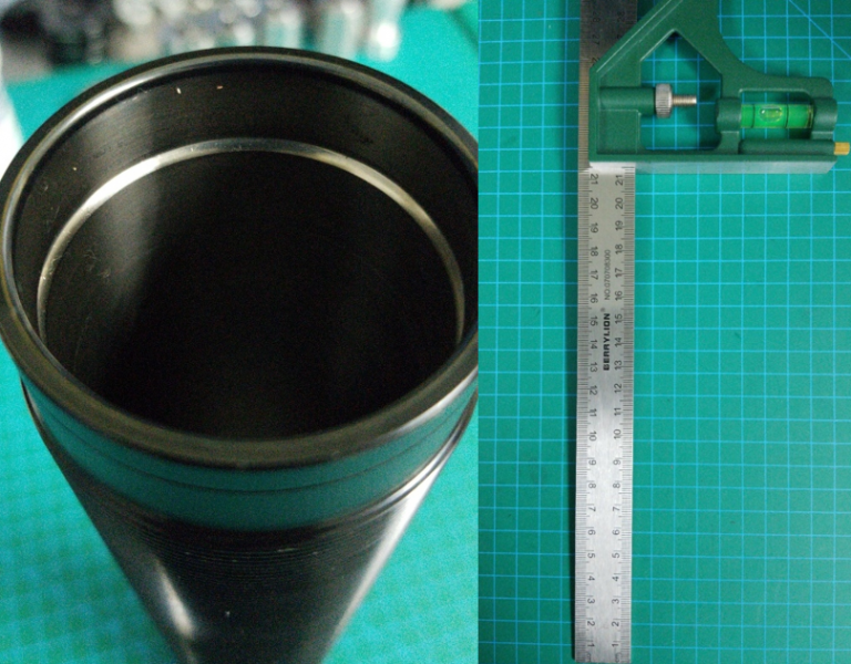
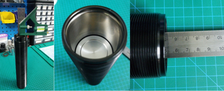
Damper Bodies
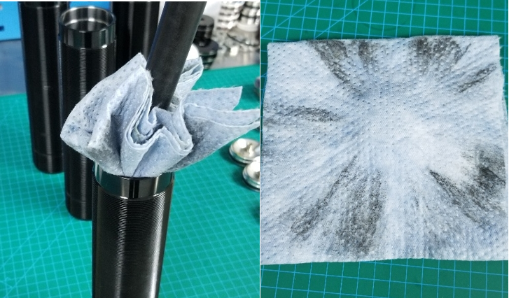
Using lint-free cloth/towels, make sure to clean out the insides of each damper body before use. Spray some brake cleaner inside to ensure they are silky smooth!
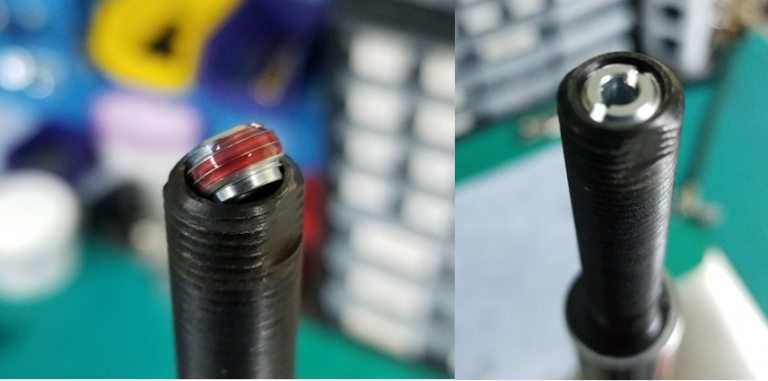
Bleed Needle & Jet Valve
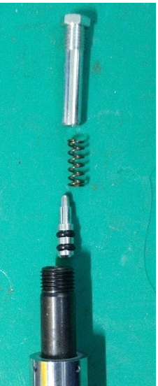
Please note the orientation of the bleed needle, spring and jet valve. These insert into the end of the piston rod in this order
Use a small amount of thread locker on the end of the jet valve. Carefully HAND TIGHTEN the jet valve into the end of the piston rod and STOP when it is fully inserted. DO NOT OVER TIGHTEN or you will snap the end off the jet valve
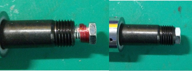
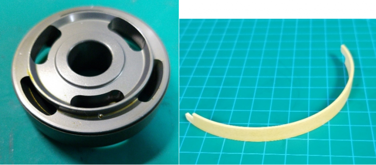
Bump Stop Orientation
Notice the type of bump shims for the 14mm and 20mm OD rods (flat for 14mm rods, 5mm/10mm for 20mm rods), and the correct orientation of the PU bump stops. DO NOT install these the wrong way otherwise it will block the bleed flow
Piston Bleed Hole
There is a 1.5mm bleed hole on one side of the piston. This helps with bleeding air from the damper when pumping the rod. Orientation doesn’t matter, but you should install it facing down so that you don’t get oil all over your face when pumping the shaft :p
Use a good amount of Seal Butter on the outer side of the piston band to reduce friction and create a tighter seal with the damper body
Shim Assembly
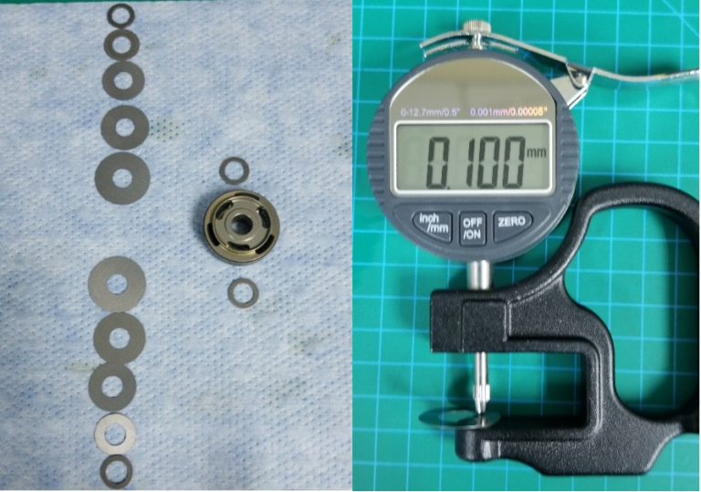
You MUST measure each and every shim to shim-match, and thoroughly clean them with a lint-free cloth. This ensures left/right dampers match
For assistance with calculating what shim stacks to use, please feel free to play around with our Chassis Calculator.
Top Shims: Compression
1 x 18mm OD * 1.00mm thick spacer shim
1 x 23mm OD * desired thickness
1 x 27mm OD * desired thickness
1 x 30mm OD * desired thickness
1 x 34mm OD * desired thickness
1 x 18mm OD * desired thickness pre-load shim
Piston goes in the middle. Notice the pre-load shim. This goes on both sides
Bottom Shims: Rebound
1 x 18mm OD * desired thickness pre-load shim
1 x 34mm OD * desired thickness
1 x 30mm OD * desired thickness
1 x 27mm OD * desired thickness
1 x 23mm OD * desired thickness
1 x 18mm OD * 1.00mm thick spacer shim
Rebound shims go on the bottom. Notice the Spacer Shim on the end. This goes on both sides
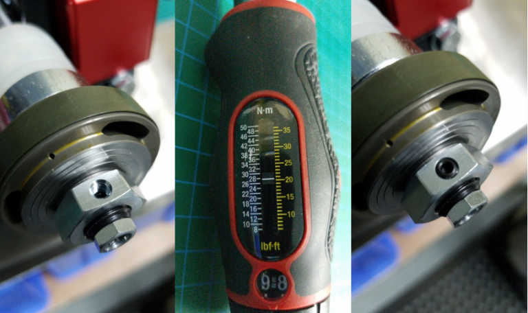
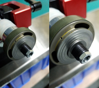
Thread the lock nut onto the end till it is tight, then torque the nut to 28nm. You do not need to use thread locker nor stake the nut. Finally secure the nut with a set screw. Do not overtighten the set screw or you will damage the threads on the rod
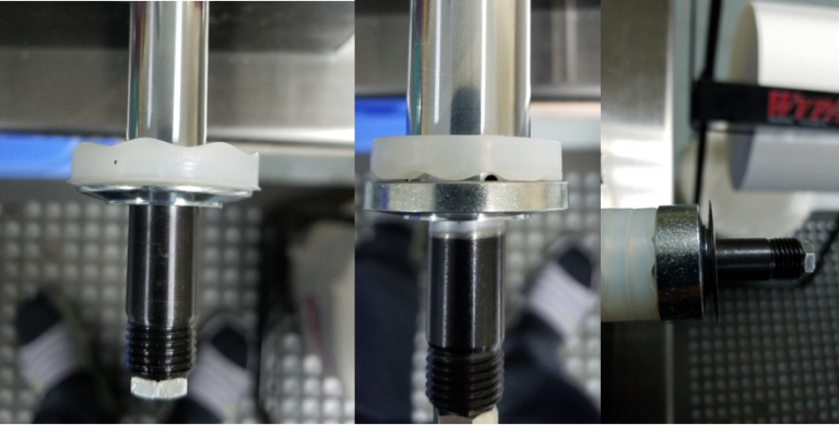
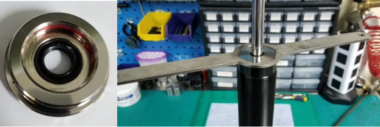
Set Seal Block Height
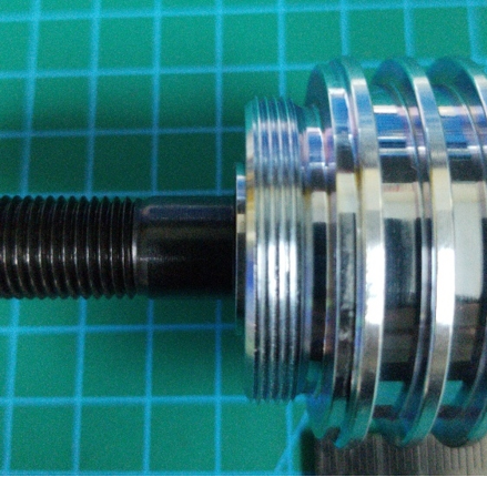
Seal block should be slid onto the piston rod using a Seal Block Bullet to prevent damage to the PU seal. The piston rod should stick out around 2mm above the end of the seal block
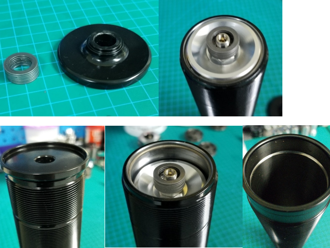
Set Floating Piston Depth
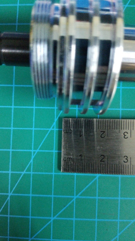
Measuring from this point (where the c-clip seats), measure the distance to the end of the piston rod (end of the jet valve)
The depth of the C-Clip groove on the damper body is 12mm from the top of the damper body. So to calculate the depth to set:
Measured length + 12mm + 8mm = Piston Depth
The reason for adding 8mm is because the floating piston will move up a few mm when you put the end cap on
After setting the floating piston depth, for future reference, you can measure the depth from the bottom which will tell you where the floating piston should sit depending on the piston rod length and damper body length
Installing the End Cap
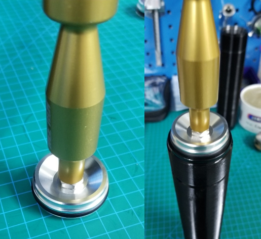
Using an end-cap tool, insert the end cap into the end of the damper body. This will push the floating piston up a few mm (hence the reason for adding 8mm when setting the depth)
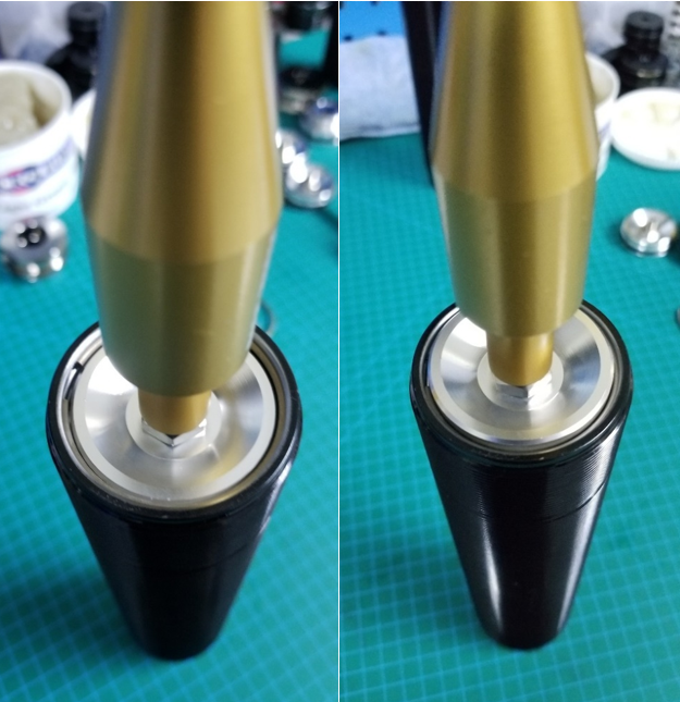
Push the end cap down far enough so that you can insert the c-clip into the groove, then pull the end cap back up till it is seated correctly
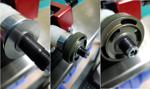
Preparing to bleed
Create a spacer using 7 x 18*1mm shims (or a lock nut) and, using one of the thrust bearing steel covers, push the end cap up and into the damper body. This will sit around 15mm into the damper body i.e Just slightly more than the depth of the c-clip groove from the top of the damper body
Next, clamp the damper body with a vice with the spacer/cover sitting flat on the bottom. With the damper body in the vice, make sure the damper body and spacer/cover is securely held together; this prevents the floating piston/end cap from compressing all the way to the bottom during bleeding, which will make it very difficult when it comes time to position the seal block and c-clip at the top after bleeding
Bleed and seal the Damper
Using a small amount of threadlocker on the end cap, tighten it down using a hex tool or our Top Cap Remover
Install the Bleed Adjuster
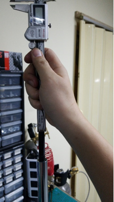
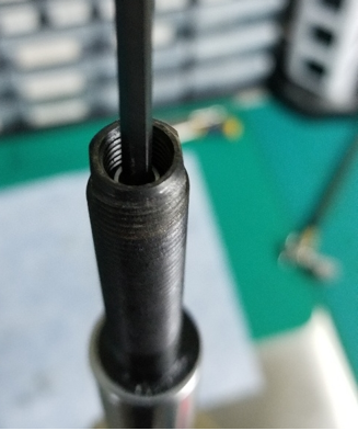
Insert the bleed rod into the top of the piston rod and then, using a caliper, push down on the needle rod to take a measurement. The end measurement you want is 27mm from the top of the piston rod
e.g If, after pushing down on the rod it shows 20mm. This means that the bleed rod you inserted is 7mm too long. Grind down the rod by 7mm then re-measure. If you done it correctly, it should now be 27mm
Why 27mm? Because our threaded adjuster + adjuster cap is 23mm long. The bleed needle adjustment is 4mm, so 23 + 4 = 27mm at zero bleed (i.e full clockwise/hard)
Once the correct distance is set, insert the threaded adjuster (with balls + spring) into the rod and thread it all the way down to the bottom as far as it will go with an allen key. You will then turn the adjuster anti-clockwise by 4 full rotations (approx. 32 clicks). 1 full rotation = 1mm, so 4mm of bleed requires 4 full rotations
If done correctly, the adjuster cap should sit flush with the top once tightened down. Make sure to add a little bit of threadlocker to the adjuster cap so that it doesn’t come loose and let it dry for a few hours before using the adjuster so as not to upset the position of the adjuster cap (although we do recommend doing 1-2 clicks clockwise after the adjuster cap is tightened down. This is to prevent the threadlocker from bonding the adjuster cap to the threaded adjuster)
Charge your damper with Nitrogen
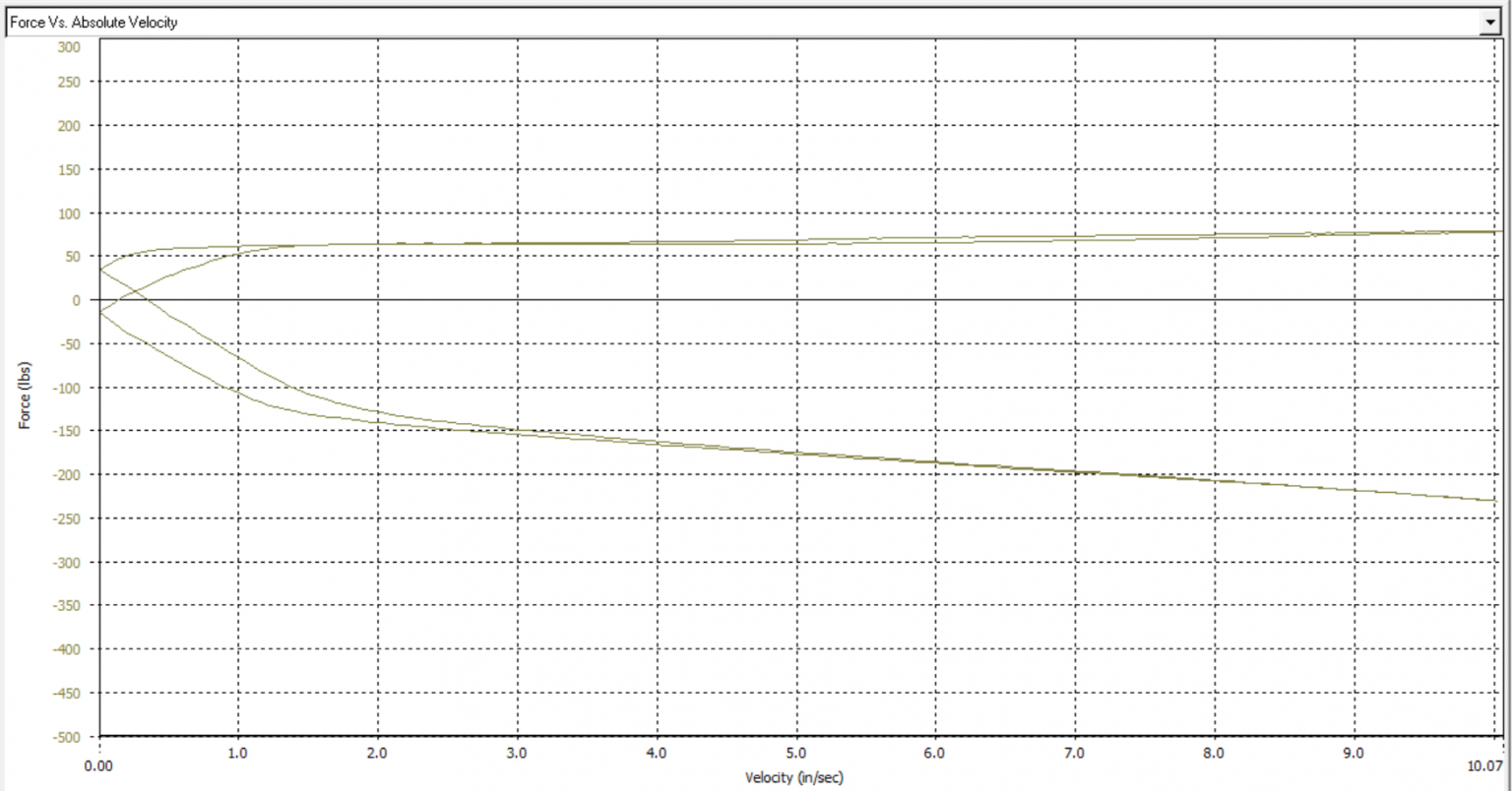
If you do not have access to a shock dyno, unfortunately, you will not be able to pressure-tune your damper:
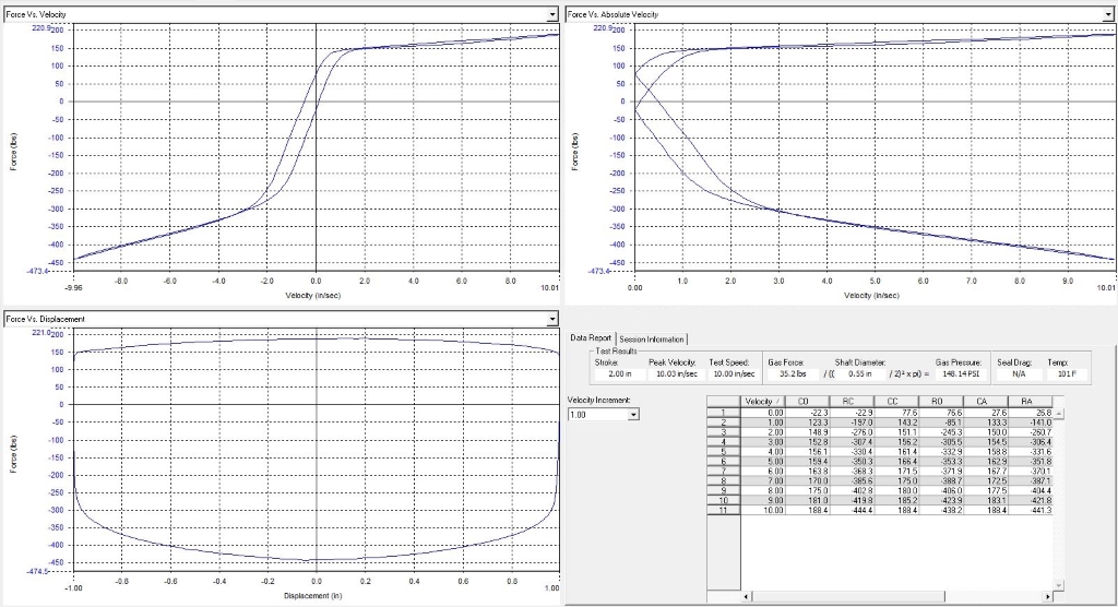
An example of a bad curve from one of the "Big 3" Europeans. Significant hysteresis and cavitation

We sincerely hope that this guide has given you some insight into how monotube dampers work, and how to rebuild/re-valve them. If you have any questions or feedback, we would like to hear from you.
Damper Bodies
Using lint-free cloth/towels, make sure to clean out the insides of each damper body before use. Spray some brake cleaner inside to ensure they are silky smooth!
Bleed Needle & Jet Valve
Please note the orientation of the bleed needle, spring and jet valve. These insert into the end of the piston rod in this order
Use a small amount of thread locker on the end of the jet valve. Carefully HAND TIGHTEN the jet valve into the end of the piston rod and STOP when it is fully inserted. DO NOT OVER TIGHTEN or you will snap the end off the jet valve
Bump Stop Orientation
Notice the type of bump shims for the 14mm and 20mm OD rods (flat for 14mm rods, 5mm/10mm for 20mm rods), and the correct orientation of the PU bump stops. DO NOT install these the wrong way otherwise it will block the bleed flow
Piston Bleed Hole
There is a 1.5mm bleed hole on one side of the piston. This helps with bleeding air from the damper when pumping the rod. Orientation doesn’t matter, but you should install it facing down so that you don’t get oil all over your face when pumping the shaft :p
Use a good amount of Seal Butter on the outer side of the piston band to reduce friction and create a tighter seal with the damper body
Shim Assembly
You MUST measure each and every shim to shim-match, and thoroughly clean them with a lint-free cloth. This ensures left/right dampers match
For assistance with calculating what shim stacks to use, please feel free to play around with our Chassis Calculator.
Top Shims: Compression
1 x 18mm OD * 1.00mm thick spacer shim
1 x 23mm OD * desired thickness
1 x 27mm OD * desired thickness
1 x 30mm OD * desired thickness
1 x 34mm OD * desired thickness
1 x 18mm OD * desired thickness pre-load shim
Piston goes in the middle. Notice the pre-load shim. This goes on both sides
Bottom Shims: Rebound
1 x 18mm OD * desired thickness pre-load shim
1 x 34mm OD * desired thickness
1 x 30mm OD * desired thickness
1 x 27mm OD * desired thickness
1 x 23mm OD * desired thickness
1 x 18mm OD * 1.00mm thick spacer shim
Rebound shims go on the bottom. Notice the Spacer Shim on the end. This goes on both sides
Thread the lock nut onto the end till it is tight, then torque the nut to 28nm. You do not need to use thread locker nor stake the nut. Finally secure the nut with a set screw. Do not overtighten the set screw or you will damage the threads on the rod
Set Seal Block Height
Seal block should be slid onto the piston rod using a Seal Block Bullet to prevent damage to the PU seal. The piston rod should stick out around 2mm above the end of the seal block
Set Floating Piston Depth
Measuring from this point (where the c-clip seats), measure the distance to the end of the piston rod (end of the jet valve)
The depth of the C-Clip groove on the damper body is 12mm from the top of the damper body. So to calculate the depth to set:
Measured length + 12mm + 8mm = Piston Depth
The reason for adding 8mm is because the floating piston will move up a few mm when you put the end cap on
After setting the floating piston depth, for future reference, you can measure the depth from the bottom which will tell you where the floating piston should sit depending on the piston rod length and damper body length
Installing the End Cap
Using an end-cap tool, insert the end cap into the end of the damper body. This will push the floating piston up a few mm (hence the reason for adding 8mm when setting the depth)
Push the end cap down far enough so that you can insert the c-clip into the groove, then pull the end cap back up till it is seated correctly
Preparing to bleed
Create a spacer using 7 x 18*1mm shims (or a lock nut) and, using one of the thrust bearing steel covers, push the end cap up and into the damper body. This will sit around 15mm into the damper body i.e Just slightly more than the depth of the c-clip groove from the top of the damper body
Next, clamp the damper body with a vice with the spacer/cover sitting flat on the bottom. With the damper body in the vice, make sure the damper body and spacer/cover is securely held together; this prevents the floating piston/end cap from compressing all the way to the bottom during bleeding, which will make it very difficult when it comes time to position the seal block and c-clip at the top after bleeding
Bleed and seal the Damper
- Insert the built rod into the damper body, with the piston around an inch below the c-clip groove. Double check to make sure the seal block is in the correct position (2mm of the rod sticking out)
- Add oil up to the top of the damper body, and swirl the rod down an inch. The swirling will help release some air from the oil
- Repeat no.2 until the bottom of the seal block is around 5mm above the top of the damper body
- Slowly swirl the rod back up the damper body. Make sure the oil line is above the bump stop and doesn’t drop below it. If it does, air will get in and you will have to start again from the beginning
- Pump the rod up down as in 2-4 (you don’t need to add more oil), whilst tapping the damper body wall with a mallet/hands. This helps free any trapped air pockets
- Keep doing this around 10 times. If you still see air bubbles in the oil, repeat no.5
- Once finished, swirl the rod down so that there is a 5mm gap between the bottom of the seal block and top of the damper body, and top up the damper with oil. Next, using a mallet, tap the rod and seal block down into the damper body (oil will overflow out. If it doesn't, it means you did not top it up with enough oil. This is to ensure no more air is left inside), making sure the seal block stays in position around 2mm below the piston rod end (you can use a socket to make sure it doesn’t pop off the top)
- Once the seal block is securely in the damper body (just enough that the o-ring(s) are fully inside), remove the spacer/cover, which will now make it much easier to seal the damper. Using a mallet, tap the rod and seal block down just far enough so that you can see the groove in the damper body to insert the c-clip
- Once the c-clip is secure, you can pull the rod up slightly until the seal block is flush with the c-clip
- Congratulations; you have now successfully bled your damper
Using a small amount of threadlocker on the end cap, tighten it down using a hex tool or our Top Cap Remover
Install the Bleed Adjuster
Insert the bleed rod into the top of the piston rod and then, using a caliper, push down on the needle rod to take a measurement. The end measurement you want is 27mm from the top of the piston rod
e.g If, after pushing down on the rod it shows 20mm. This means that the bleed rod you inserted is 7mm too long. Grind down the rod by 7mm then re-measure. If you done it correctly, it should now be 27mm
Why 27mm? Because our threaded adjuster + adjuster cap is 23mm long. The bleed needle adjustment is 4mm, so 23 + 4 = 27mm at zero bleed (i.e full clockwise/hard)
Once the correct distance is set, insert the threaded adjuster (with balls + spring) into the rod and thread it all the way down to the bottom as far as it will go with an allen key. You will then turn the adjuster anti-clockwise by 4 full rotations (approx. 32 clicks). 1 full rotation = 1mm, so 4mm of bleed requires 4 full rotations
If done correctly, the adjuster cap should sit flush with the top once tightened down. Make sure to add a little bit of threadlocker to the adjuster cap so that it doesn’t come loose and let it dry for a few hours before using the adjuster so as not to upset the position of the adjuster cap (although we do recommend doing 1-2 clicks clockwise after the adjuster cap is tightened down. This is to prevent the threadlocker from bonding the adjuster cap to the threaded adjuster)
Charge your damper with Nitrogen
If you do not have access to a shock dyno, unfortunately, you will not be able to pressure-tune your damper:
- Typical range for a 14mm OD rod is 150-200psi
- Typical range for a 20mm OD rod is 100-150psi
- If you require assistance/advice on what to charge your damper to, please Contact Us
- Initially charge the damper to ~100psi
- Set the bleed adjuster to 2mm (2 full rotations from full-soft or full-hard). We always recommend setting the base damping forces that you calculated at 2mm bleed (the middle adjustment setting) as this allows you to fine-tune the bleed settings on your car (soft/hard) without causing too big a swing in internal pressures. This is in stark contrast to some manufacturers that valve their dampers at 0mm bleed and then expect you to turn down the damping to meet your base damping forces. Not very targeted, is it?
- After running a Force vs Absolute Velocity sweep, check for any signs of hysteresis and/or cavitation. If the damper has cavitation, you will hear the squishing sound of the oil vaporising during the compression stroke
- Typically, if you find hysteresis, you need to lower the gas pressure. Conversely, if you find cavitation, you need to increase the gas pressure
- If, even after lowering the gas pressure, you still have hysteresis and you can't lower it further due to cavitation, most of the time this is due to insufficient gas chamber volume. A tell-tale sign is your internal gas spring pressure (gas force) going through the roof (you want this as low as possible)
- Rinse & repeat until you have the absolute minimum amount of hysteresis possible (the curves are as close together as possible), and no signs of cavitation
An example of a bad curve from one of the "Big 3" Europeans. Significant hysteresis and cavitation
We sincerely hope that this guide has given you some insight into how monotube dampers work, and how to rebuild/re-valve them. If you have any questions or feedback, we would like to hear from you.